What is STP?
Spanning Tree Protocol (STP) is a network protocol designed to prevent layer 2 loops. It is standardized as IEEE 802.D protocol. STP blocks some ports on switches with redundant links to prevent broadcast storms and ensure loop-free topology. With STP in place, you can have redundant links between switches in order to provide redundancy.
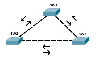
To better understand the importance of STP and how STP prevents broadcast storms on a network with redundant links, consider the following example:

SW1 sends a broadcast frame to SW2 and SW3. Both switches receive the frame and forward the frame out every port, except the port the frame was received on. So SW2 forwards the frame to SW3. SW3 receives that frame, and forwards it to SW1. SW1 then again forwards the frame to SW2! The same thing also happens in the opposite direction. Without STP in place, these frames would loop forever. STP prevents loops by placing one of the switch ports in blocking state.
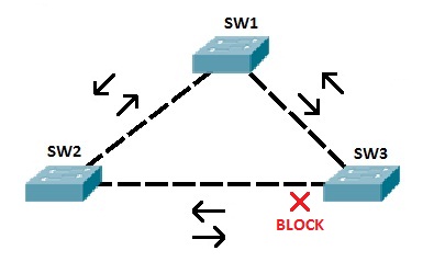
So, our toplogy above could look like this:

In the topology above, STP has placed one port on SW3 in the blocking state. That port will no longer process any frames except the STP messages. If SW3 receives a broadcast frame from SW1, it will not forward it out the port connected to SW2.NOTE
STP enables layer 2 redundancy. In the example above, if the link between SW3 and SW1 fails, STP would converge and unblock the port on SW3.
How STP works
STP uses the Spanning-Tree Algorithm (SPA) to create a topology database of the network. To prevent loops, SPA places some interfaces in forwarding state and other interfaces in blocking state. How does STP decides in which state the port will be placed? A couple of criteria exist:
1. all switches in a network elect a root switch. All working interfaces on the root switch are placed in forwarding state.
2. all other switches, called nonroot switches, determine the best path to get to the root switch. The port used to reach the root switch (root port) is placed in forwarding state.
3. on the shared Ethernet segments, the switch with the best path to reach the root switch is placed in forwarding state. That switch is called the designated switch and its port is known as the designated port.
4. all other interfaces are placed in blocking state and will not forward frames.NOTE
STP considers only working interfaces – shutdown interfaces or interfaces without the cable installed are placed in an STP disabled state.
An example will help you understand the concept:

Let’s say that SW1 is elected as the root switch. All ports on SW1 are placed into forwarding state. SW2 and SW3 choose ports with the lowest cost to reach the root switch to be the root ports. These ports are also placed in forwarding state. On the shared Ethernet segment between SW2 and SW3, port Fa0/1 on SW2 has the lowest cost to reach the root switch. This port is placed in forwarding state. To prevent loops, port Fa0/1 on SW3 is placed in blocking state.NOTE
A switch with the lowest switch ID will become the root switch. A switch ID consists of two components: the switch’s priority (by default 32,768 on Cisco switches) and the switch’s MAC address.
BPDU (Bridge Protocol Data Unit)
BPDUs are messages used by switches to share STP information with each other in order to elect a root switch and detect loops. The most common messages are Hello BPDUs which include the following information:
- root switch ID
- sender’s switch ID
- sender’s root cost
- Hello, MaxAge, and forward delay timers
Electing the Root Switch in STP
The STP process works by default on Cisco switches and begins with the root switch election. The election is based on the bridge IDs (BIDs) sent in the BPDUs. Each switch that participates in STP will have a 8-byte switch ID that comprises of the following fields:
- 2-byte priority field – by default, all switches have the priority of 32768. This value can be changed using configuration commands.
- 6-byte system ID – a value based on the MAC address of each switch.
A switch with the lowest BID will become a root switch, with lower number meaning better priority.
Consider the following example:

As mentioned above, the switch with the lower BID wins. Since by default all switches have the BID priority of 32768, the second comparison has to be made – the lowest MAC address. In our example SW1 has the lowest MAC address and becomes the root switch.NOTE
For simplicity, all ports on switches in the example above are assigned to VLAN 1. Also, note that STA adds the VLAN number to the priority value, so all switches actually have the BID priority of 32,769.
To influence the election process, you can change the BID priority to a lower value on a switch you would like to become root. This can be done using the following command:
(config)#spanning-tree vlan ID priority VALUE
The priority must be in increments of 4096, so if you choose any other value, you will get en error and possible values listed:
(config)#spanning-tree vlan 1 priority 224
% Bridge Priority must be in increments of 4096.
% Allowed values are:
0 4096 8192 12288 16384 20480 24576 28672
32768 36864 40960 45056 49152 53248 57344 61440
(config)#spanning-tree vlan 1 priority 4096
Selecting STP root port
As we’ve mentioned before, all working interfaces on the root switch are placed in forwarding state. All other switches (called nonroot switches) determine the best path to get to the root switch and the port used to reach the root switch is placed in forwarding state. The best path is the one with the lowest cost to reach the root switch. The cost is calculated by adding the individual port costs along the path from the switch to the root.
Take a look the following example:

SW1 has won the election process and is the root switch. Consider the SW3’s perspective for choosing its root port. Two paths are available to reach the root switch, one direct path over Fa0/1 and the other going out Fa0/2 and through SW2. The direct path has a cost of 19, while the indirect path has the cost of 38 (19+19). That is why Fa0/1 will become the root port on SW3.
In case the best root cost ties for two or more paths, the following tiebreakers are applied:
- the lowest neighbor bridge ID
- the lowest neighbor port priority
- the lowest neighbor internal port number
The default port cost is defined by the operating speed of the interface:
| Speed | Cost |
|---|---|
| 10 Mbps | 100 |
| 100 Mbps | 19 |
| 1 Gbps | 4 |
| 10 Gbps | 2 |
You can override the default value on the per-interface basis using the following command:
(config-if)#spanning-tree cost VALUE
Selecting STP designated port (DP)
We’ve already learned that, on the shared Ethernet segments, the switch with the best path to reach the root switch is placed in forwarding state. That switch is called the designated switch and its port is known as the designated port. In order to avoid loops, the non-designated port on the other end of the link is placed in blocking state.
The designated switch is determined based on the following criteria:
- the switch with the lowest cost to reach the root becomes the designated switch on that link.
- in case of a tie, the switch with the lowest BID becomes the designated switch.
Consider the following example:

SW1 has the lowest BID and has been selected as the root switch. SW2 and SW3 have then determined their own root port to reach the root switch. On the shared network segment between SW2 and SW3 a designated port needs to be selected. Because SW3 has the lower cost to reach the root switch (4<19), its Fa0/2 port will be the designated port for the segment. The Fa0/2 port on SW2 will be placed in blocking state.NOTE
If the link between SW1 and SW3 fails, STP will converge and the Fa0/2 port on SW2 will be placed in the forwarding state.