Configuring OSPF 1
OSPF’s basic configuration is very simple. Just like with other routing protocols covered so far (RIP, EIGRP) first you need to enable OSPF on a router. This is done by using the router OSPF PROCESS-ID global configuration command. Next, you need to define which interfaces OSPF will run and what networks will be advertised. This is done by using the network IP_ADDRESS WILDCARD_MASK AREA_ID command from the OSPF configuration mode.NOTE
The OSPF process number doesn’t have to be the same on all routers in order to establish a neighbor relationship, but the Area ID has to be the same on all neighboring routers in order for routers to become neighbors.
Let’s get started with some basic OSPF configuration. We will use the following network topology:

First, we need to enable OSPF on both routers. Then we need to define what network will be advertised into OSPF. This can be done by using the following sequence of commands on both routers:


The network commands entered on both routers include subnets directly connected to both routers. We can verify that the routers have become neighbors by typing the show IP OSPF neighbors command on either router:

To verify if the routing updated were exchanged, we can use the show ip route command. All routes marked with the character O are OSPF routes. For example, here is the output of the command on R1:

You can see that R1 has learned about the network 192.168.0.0/24 through OSPF.
Configuring OSPF 2
Although basic OSPF configuration can be very simple, OSPF provides many extra features that can get really complex. In this example, we will configure a multi-area OSPF network and some other OSPF features.
Consider the following multiarea OSPF network:

In this example we have two OSPF areas – area 0 and area 1. As you can see from the network topology depicted above, routers R1 and R3 are in the area 0 and area 1, respectively. Router 2 connects to both areas, which makes him an ABR (Area Border Router). Our goal is to advertise the subnets directly connected to R1 and R3. To do that, the following configuration on R1 will be used:

NOTE
We have used the router-id 1.1.1.1 command to manually specify the router ID of this router. OSPF process will use that RID (router-id) when communicating with other OSPF neighbors.
Because R1 connects only to R2, we only need to establish a neighbor relationship with R2 and advertise directly connected subnet into OSPF.
Configuration of R3 looks similar, but with one difference, namely area number. R3 is in area 1.

What about R2? Well, because R2 is an ABR, we need to establish neighbor relationship with both R1 and R3. To do that, we need to specify different area ID for each neighbor relationship, 0 for R1 and 1 for R2. We can do that using the following sequence of commands:

Now R2 should have neighbor relationship with both R1 and R3. We can verify that by using the show ip ospf neighbor command:

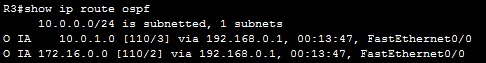
To verify if directly connected subnets are really advertised into the different area, we can use the show ip route ospf command on both R1 and R3:

Characters IA in front of the routes indicates that these routes reside in different areas.NOTE
Since they reside in different areas, R1 and R3 will never establish a neighbor relationship.
Designated & Backup Designated Router
Based on the network type, the OSPF router can elect one router to be a Designated Ruter (DR) and one router to be a Backup Designated Router (BDR). For example, on multiaccess broadcast networks (such as LANs) routers defaults to elect a DR and BDR. DR and BDR serve as the central point for exchanging OSPF routing information. Each non-DR or non-BDR router will exchange routing information only with the DR and BDR, instead of exchanging updates with every router on the network segment. DR will then distribute topology information to every other router inside the same area, which greatly reduces OSPF traffic.
To send routing information to a DR or BDR the multicast address of 224.0.0.6 is used. DR sends routing updates to the multicast address of 224.0.0.5. If DR fails, BDR takes over its role of redistributing routing information.
Every router on a network segment will establish a full neighbor relationship with the DR and BDR. Non-DR and non-BDR routers will establish a two-way neighbor relationship between themselves.NOTE
On point-to-point links, a DR and BDR are not elected since only two routers are directly connected.
On LANs, DR and BDR have to be elected. Two rules are used to elect a DR and BDR:
- router with the highest OSPF priority will become a DR. By default, all routers have a priority of 1.
- if there is a tie, a router with the highest router ID wins the election. The router with the second highest OSPF priority or router ID will become a BDR.
To better understand the concept, consider the following example.

All routers depicted above are in the same area (area 0). All routers are running OSPF. Routers R1 and R2 have been elected as DR and BDR because they have the highest and the second highest router ID (100.0.0.0 and 90.0.0.0 respectively). If, for example, R3’s directly connected subnet fails, R3 informs R1 and R2 (the DR and BDR for the segment) of the network change (step 1). R1 then informs all other non-DR and non-BDR routers of the change in topology (step 2).
We can verify that R1 and R2 are indeed the DR and BDR of the segment by typing the show ip ospf neighbors command on R3:
R3#show ip ospf neighbor


Neighbor ID     Pri   State           Dead Time   Address         Interface
60.0.0.0          1   FULL/DROTHER    00:00:33    10.0.0.5        FastEthernet0/0
100.0.0.0         1   FULL/DR         00:00:33    10.0.0.1        FastEthernet0/0
70.0.0.0          1   FULL/DROTHER    00:00:33    10.0.0.4        FastEthernet0/0
90.0.0.0          1   FULL/BDR        00:00:33    10.0.0.2        FastEthernet0/0
NOTE
You can influence the DR and BDR election process by manually configuring the OSPF priority. This is done by using the ip ospf priority VALUE command interface command.