In this section, we will focus mainly on the ARMv8-A exceptions, the role of ARM Trusted Firmware (that provides Secure Monitor functionality), and how the World Switch happens between Secure and Normal. If we look at the architectural diagram of ARM Trust zone w.r.t ARMv8-A, the Execution Level is divided into four levels namely:
- EL0 (Secure & Non-Secure) – User Application
- EL1 (Secure & Non-Secure) – Kernel
- EL2 – Hypervisor for running different OS’s simuntaneously
- EL3 – Security Monitor

Now, whenever a normal world User Application calls for some Secure Operation, the calls goes via IOCTL call to the Linux Driver, which ultimately calls the smc instruction. To understand what the smc instruction, we have to look on the Exceptions in ARMv8
ARMv8 Exceptions
In ARMv8 the exceptions are divided into two categories: Synchronous & Asynchronous. An exception is described as synchronous if it is generated as a result of execution or attempted execution of the instruction stream, and where the return address provides details of the instruction that caused it. An asynchronous exception is not generated by executing instructions, while the return address might not always provide details of what caused the exception.
Source of Asynchronous Exception can be:
- IRQ (normal priority Interrupt)
- FIQ (Fast Interrupt)
- System ERROR
While the Source of Synchronous Exceptions can be:
- Aborts from the MMU.
- Unallocated instructions.
- Service Calls (SVCs, SMCs and HVCs).
AARCH64 Exception Table
Unlike the lower version of ARM, ARMv8 don’t implement dedicated handler for SMC instructions. The table effectively consists of 4 sets of 4 entries. Which entry is used depends upon a number of factors:
- The type of exception (SError, FIQ, IRQ or Synchronous)
- If the exception is being taken at the same Exception level, the Stack Pointer to be used (SP0 or SPx).
- If the exception is being taken at a lower Exception level, the execution state of the next lower level (AArch64 or AArch32)
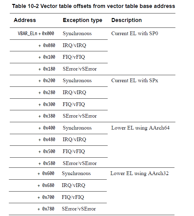
Now, let’s say our Linux Kernel is using the AARCH64 execution state. Thus, when it execute the smc instruction, the handler on the address VBAR_EL3 + 0x400 will be executed.Now let us understand the significance of some of the important registers of ARMv8 that are required to handle the exceptions and switch world.
Registers for handling exceptions
1. SPSR_ELn (Saved Program Status Register)
When taking an exception, the processor state is stored in the relevant Saved Program StatusRegister (SPSR), in a similar way to the CPSR in ARMv7. The SPSR holds the value of PSTATEbefore taking an exception and is used to restore the value of PSTATE when executing anexception return.

For more info on the significance of each bit, check the Architectural Reference Manual given in the References below at the end.
2. ELR_ELn (Exception Link Register)
The Exception Link Register holds the address to return to after an exception. Thus, both the SPSR and ELR register are necessary, while returning from the exception handler. The figure shows what would happen if the processor core have to serve some interrupt while it is in EL0.

3. ESR_ELn (Exception Syndrome Register)
The Exception Syndrome Register, ESR_ELn, contains information which allows the exception handler to determine the reason for the exception. It is updated only for synchronous exceptions and SError. Bits [31:26] of ESR_ELn indicate the exception class which allows the handler to distinguish between the various possible exception causesBits [24:0] form the Instruction Specific Syndrome (ISS) field containing information specific to that exception type. For example, when a system call instruction (SVC, HVC or SMC) is executed, the field contains the immediate value associated with the opcode such as 0x123456 for SVC 0x123456.
4. SCR_EL3 (Secure Configuration Register)
The security register is configured by the EL3 monitor. The most important bit that is used to distinguish between the two worlds is the SCR_EL3.NS bit. When NS=1, means non-secure, while NS=0, means core is in secure.
5. VBAR_ELn (Vector Base Address Register) –
Each Exception level has its own vector table, that is, there is one for each of EL3, EL2 and EL1. The table contains instructions to be executed, rather than a set of addresses. Vectors for individual exceptions are located at fixed offsets from the beginning of the table. The virtual address of each table base is set by the Vector Based Address Registers VBAR_EL3, VBAR_EL2 and VBAR_EL1.
Thus, on boot time the Secure Monitor fill the VBAR_EL3 with the base address of the Exception table, for the exceptions to be handled in EL3. Now, if the Linux kernel (non-secure) calls the smc instruction, the corresponding instruction is handled by the VBAR_EL3 + 0x400 (provided kernel is in ARCH64 state).Then reading the ESR_EL3, the monitor code decides that the system call is of SMC type and the smc_handler64() is being executed. Till now on, processor is on EL3, inside the smc handler, now what is next? How the EL3 Monitor will do a world switch?
Next topic to be discuss is the Secure world initialization during Boot Time. According to Arm Trusted Firmware, the booting of a ARMv8 based system is divided into different stages namely BL1 (generally the BOOTROM code), BL2 (uboot/lk), BL31 (Secure Monitor Code), BL32 (TEE) & BL33 (Linux Kernel). Note that this stages are vary w.r.t the SoC design.
1. Thus when the execution is passed over the ATF (BL31) by the bootloader, it does some basic architectural and platform initialization and passes the control over to TEE (BL32). If we make some pseudo-code, it would look something like:
NOTE that in these pseudo-code we will not take Exception masking in consideration.Pseudo codes inside BL31 Secure Monitor
uint64_t el3_BL32_init(){
save_current_SP_in stack(global_ctx);
save_x0_to_x31_in _stack(global_ctx);
configure_SPSR();
configure_SCR();
SCR.NS = 0;
configure_ELR(TEE_BASE_ADDRESS);
// x0 to x4 may contain some additional info like DT address
eret();
// once the TEE is been initialized, the stack will be restored by SMC handler and the execution will resume from here}
uint64_t el3_smc_handler_64(uint64_t x0, uint64_t x1, …){ uint64_t smc_id = x0;
switch(smcid) {
case SMC_TEE_INIT_DONE:
save_vector_table(x1);
restore_stack_pointer(global_ctx);
restore_x0_to_x31_from _stack(global_ctx);
return;
…
…
}
}
Pseudo code inside TEE
struct tee_vector_table { uint64_t (*std_smc_entry)(uint64_t x0, uint64_t x1, uint64_t x2, uint64_t x3); uint64_t (*std_fast_entry)(uint64_t x0, uint64_t x1, uint64_t x2, uint64_t x3); … …} global_vector_table;
_tee_start(){ // Do the initial architectural & platform initialization like mmu cache setup
…
…
x1 = tee_init_vector_table();
x0 = SMC_TEE_INIT_DONE;
call_smc();}
struct tee_vector_table *tee_init_vector_table(){
global_vector_table.std_smc_entry = tee_std_smc_entry;
…
…
return &global_vector_table;}
uint64_t tee_std_smc_entry(uint64_t x0, uint64_t x1, uint64_t x2, uint64_t x3){ …}Thus when the system gets boot-up, the EL3 Monitor Code initializes the TEE, which returns the vector table consisting of the address of different handlers such as Fast SMC, Standard SMC, PSCI’s, etc.
2. Now once the TEE initialization is done, how the SMC is going to be hand over to TEE by Secure Monitor? This can be explained by the pseudo-code below:
From normal world the TEE driver need to call the smc like:
tee_driver_call_smc(uint64_t x0, uin64_t x1, uin64_t x2, uin64_t x3, uin64_t x4)
{
x0 = STD_SMC_ID_XYZ;
x1_to_x4_holds_params();
smc();
}
Thus the exeception would handled by the smc_handler inside EL3:
uint64_t el3_smc_handler_64(uint64_t x0, uint64_t x1, …)
{
uint64_t smc_id = x0;
switch(smcid) {
case STD_SMC_ID_XYZ:
el3_secure_world_switch_std_smc(x0, x1, x2, x3, x4);
case SMC_DONE:
el3_normal_world_switch(x0, x1, x2, x3, x4);
…
}
}
uint64_t el3_secure_world_switch_std_smc(reg x0, reg x1, reg x2, reg x3, reg x4){ save_current_SP_in stack(global_ctx);
save_x0_to_x31_in _stack(global_ctx);
save_elr_in_stack(global_ctx);
configure_SPSR();
configure_SCR();
SCR.NS = 0;
configure_ELR(vector_table->std_smc_entry);
eret();
}
uint64_t el3_normal_world_switch(){
restore_current_SP_from stack(global_ctx);
restore_x0_to_x31_from _stack(global_ctx);
restore_elr_from_stack(global_ctx);
configure_SPSR();
configure_SCR();
SCR.NS = 1;
eret();
}
Thus we can conclude, EL3 monitor will follow up with the handler registered during the initial boot-up sequence, so that whenever a smc call came to EL3, that will be serviced w.r.t the specific handler, likewise in the above pseudo-code example the standard SMC call was been serviced at the Secure EL1, via the standard SMC call handler
Even though the this pseudo-code don’t deal with very deep overview like exception masking, processor states, and even more. Yet it could be referenced to understand the World switch.
Some points to be noted:
- This whole article has been focused only on the SMC call from EL1 (linux kernel). W.r.t the latest ARM spec, EL2 also has it secure and non secure state, thus the way in which the world switch happen in EL2 may or may not vary w.r.t EL1.
- The whole article is based upon ARMv8-A profile, and it don’t deals with ARMv8-M or ARMv8-R. There is totally different explanation for Armv8-M for secure world.
- You cannot call an smc call from EL0 directly. This may give an illegal instruction or hardfault.