IEEE 802.1Q is one of the VLAN tagging protocols supported by Cisco switches. This standard was created by the Institute of Electrical and Electronics Engineers (IEEE), so it an open standard and can be used on non-Cisco switches.
To identify to which VLAN a frame belongs to, a field is inserted into the frame’s header.
Original frame:


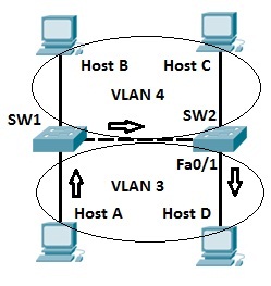
An example will attempt to clarify the concept. Let’s say that we have a network of 2 switches and 4 hosts. Hosts A and host D are in VLAN 2, while hosts B and C are in VLAN 3.
On the segment between two switches, a process called VLAN trunking is used. Let’s say that host A sends a broadcast frame. SW1 “tags” the frame by inserting the VLAN ID in the header of the frame before sending the frame to SW2. SW2 receives the frame and knows that the frame belongs to VLAN 3, so it sends the frame only to host D, since that host is in VLAN 3.
Inter-Switch Link (ISL)
Another VLAN tagging protocol is Inter-Switch Link (ISL). This protocol is Cisco proprietary, which means that, unlike 802.1Q, it can be used only between Cisco switches. It is considered to be deprecated, and newer Cisco switches don’t even support it.
ISL works by encapsulating a frame in an ISL header and trailer. The encapsulated frame remains unchanged. The VLAN ID is included in the ISL header.
Original frame:
ISL frame:

Configuring voice VLANs
Most corporate networks today use IP telephony. This means that the phones are connect to the same network and use the same cabling as other network devices, such as workstations or routers. Since offices usually have only a single UTP cable to each desk, most of the IP phones today include a small switch that enable you to connect your PC to the phone sitting on the desk, and then connect the phone to the local network.
Consider the backside of an IP telephone Yealink T21:

As you can see from the picture, this phone has two UTP ports. One port is connected to the local network, while the other port can be connected to the PC.
The port on the phone connected to the switch can carry both data and voice traffic. To enable this, we need to define two VLANs on the switch port – data VLAN and voice VLAN. Here is how we can do that:
SW1(config)#vlan 5
SW1(config)#vlan 20
SW1(config)#int fa0/1
SW1(config-if)#switchport mode access
SW1(config-if)#switchport access vlan 5
SW1(config-if)#switchport voice vlan 20
We’ve created two VLANs – VLAN 5 that will be used for data sent by the PC and VLAN 20 for IP phone’s voice traffic. We’ve then placed the port into both VLANs. The keyword voice indicates that the VLAN 20 will be a voice VLAN.
To verify that the interface indeed carries data from both VLANs, we can use the show interfaces Fa0/1 switchport command:
Switch#show interfaces fa0/1 switchport
Name: Fa0/1
Switchport: Enabled
Administrative Mode: static access
Operational Mode: static access
Administrative Trunking Encapsulation: dot1q
Operational Trunking Encapsulation: native
Negotiation of Trunking: Off
Access Mode VLAN: 5 (VLAN0005)
Trunking Native Mode VLAN: 1 (default)
Voice VLAN: 20
Administrative private-vlan host-association: none
Administrative private-vlan mapping: none
...
The lines Access Mode VLAN: 5 (VLAN0005) and Voice VLAN: 20 indicate that the interface is indeed carrying traffic from both VLANs.NOTE
Some IP phones can be automatically configured with appropriate VLANs using protocols such as LLDP or CDP. However, on some models you will need to manually configure data and voice VLANs on the phone using its web interface.
Configuring allowed VLANs
By default, all VLANs are allowed across a trunk link on a Cisco switch. We can verify that using the show interfaces trunk command:
SW1#show interfaces trunk
Port        Mode         Encapsulation  Status        Native vlan
Fa0/1       on           802.1q         trunking      1

Port        Vlans allowed on trunk
Fa0/1       1-1005

Port        Vlans allowed and active in management domain
Fa0/1       1,5,10

Port        Vlans in spanning tree forwarding state and not pruned
Fa0/1       1,5,10
In the output above you can see that all VLANs (1 through 1005) are allowed on the trunk by default.
We can prevent traffic from certain VLANs from traversing a trunk link using the following interface mode command:
(config-if)#switchport trunk allowed vlan {add | all | except | remove} vlan-list
For example, to prevent traffic from VLAN 5 to traverse the trunk link, we would use the following command:
SW1(config)#int fa0/1
SW1(config-if)#switchport trunk allowed vlan remove 5
The same command needs to be entered on the switch on the other end of the link.
To verify that the traffic from VLAN 5 will indeed be blocked from traversing a trunked link, we can enter the show interfaces trunk command again:
SW1#show interfaces trunk
Port        Mode         Encapsulation  Status        Native vlan
Fa0/1       on           802.1q         trunking      1

Port        Vlans allowed on trunk
Fa0/1       1-4,6-1005

Port        Vlans allowed and active in management domain
Fa0/1       1,10

Port        Vlans in spanning tree forwarding state and not pruned
Fa0/1       none
Notice how now only VLANs 1-4 and 6-1005 are allowed on trunk.NOTE
You can use the switchport trunk allowed vlan all interface mode command to reset the switch port to its original default setting (permitting all VLANs on the trunk).