Configuring VLANs on Switch
By default, all ports on a switch are in the VLAN 1. We can verify that by typing the show vlan command from the IOS enable mode of a switch:
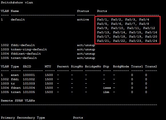
In the picture above, you can see that all of the 24 ports of the switch are in the same VLAN, namely VLAN 1.
Two steps are required to create a VLAN and assign a switch port to the VLAN:
- create a VLAN using the VLAN NUMBER global mode command
- assing a port to the VLAN by using two interface subcommands. The first command is the switch port mode access command. This command specifies that the interface is an access interface. The second command is the switch port access VLAN NUMBER command. This command assigns the interface to a VLAN.
Here is an example of assigning the VLAN 2 to the interface:

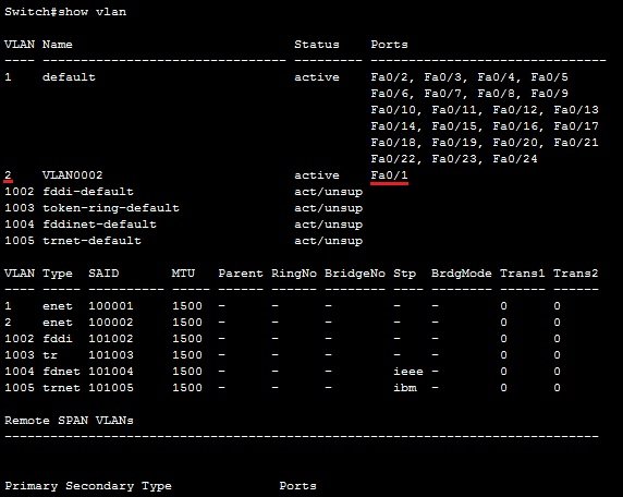
The first command (vlan 2) created the VLAN 2. We’ve then entered the Fa0/1 subinterface mode and configured the interface as an access interface that belongs to VLAN 2. To verify this, we can again use the show vlan command:
Configuring access & trunk ports
To configure an interface to be an access interface, the switchport mode acess interface command is used. This type of interface can be assigned only to a single VLAN.
To configure a trunk interface, the switchport mode trunk interface command is used. This type of interface can carry traffic of multiple VLANs.
An example will help you understand the concept.
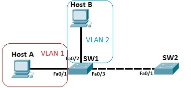
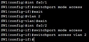
Host A and host B are in different VLANs, VLAN 1 and VLAN 2. These ports need to be configured as access ports and assigned to their respective VLANs by using the following sequence of commands:
Because the link between SW1 and SW2 needs to carry traffic of multiple VLANs, it needs to be configured as a trunk interface. This is done by using the following commands on both SW1 and SW2:
On SW1:

On SW2:

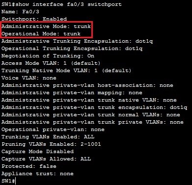
Now the link between SW1 and SW2 can carry traffic from both the VLAN1 and VLAN2. You can verify that an interface is indeed a trunk interface by using the show interface Fa0/3 switchport command on SW1:
NOTE
VLAN 1 doesn’t have to be created, it exists by default. Also, by default, all ports are in the VLAN 1, so Fa0/1 doesn’t need the switchport access vlan 1 command.
Frame tagging
To identify the VLAN a packet is belonging to, switches use tagging to assign a numerical value to each frame in a network with multiple VLANs. This is done to ensure that switches know out which ports to forward frames.
For example, consider the following network topology.
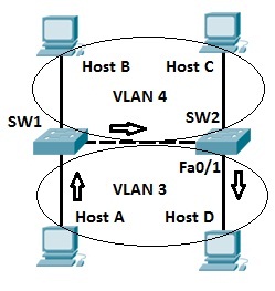
There are two VLANs in the toplogy pictured above, namely VLAN 3 and VLAN 4. Host A sends a broadcast packet to switch SW1. Switch SW1 receives the packet, tags the packet with the VLAN ID of 3 and sends it to SW2. SW2 receives the packet, looks up at the VLAN ID, and forwards the packet only out the port Fa0/1, since only that port is in VLAN 3. Host B and host C will not receive the packet because they are in different VLAN than host A.NOTE
When forwarding a tagged frame to a host device a switch will remove the VLAN tag, since host devices don’t understand tagging and would drop the packet.
Configure VLAN in Windows.
Virtual local area network (VLAN) tagging requires that the network interface card (NIC) and the router or switch that you use support protocol IEEE 802.1q.
Depending on the NIC, you can set your VLAN ID in Device Manager. Not all NICs that support VLAN tagging have this option.
Setting your VLAN ID in Device Manager
Note: Log in as the local administrator before continuing.
To open Device Manager:
- Press Windows key + R
- Type devmgmt.msc
- Click OK.
- In Device Manager, open Network adapters.
- Right-click on the NIC and choose Properties.
- Click the Advanced tab.
- Scroll down to VLAN ID.
- Set the ID that you would like the NIC to have and click OK.
Setting up your VLAN Tagging and Setting a VLAN ID
How you perform this task depends on your router or switch. Consult the manual or manufacturer of your router or switch for more details.
In your router or switch, you can VLAN tag a device by the VLAN ID if you set one previously, or by the MAC address of the computer. Your router or switch will list all IP devices by MAC address.
Configure VLAN in Linux.
To use VLAN you should first install it on your system. In Ubuntu, use the following command to install VLAN:
sudo apt-get install vlan
Now make sure that the Linux kernel driver (module) called 8021q is loaded:
lsmod | grep 8021q
If the module is not loaded, load it with the following modprobe command:
sudo modprobe 8021q
Create a new interface that is a member of a specific VLAN, we are taking VLAN id “300” and ethernet interface “eth1” in this example.
To add VLAN ID, use vconfig add command for eth1 interface:
sudo vconfig add eth1 300
The vconfig add command creates a vlan-device on eth1 which result into eth1.300 interface. You can use normal ifconfig command to check device information:
ifconfig eth1.300
Now assign IP address (we are taking 192.168.1.100 in this example, you can take yours) to vlan interface using ifconfig command:
ifconfig eth1.300 192.168.1.100 netmask 255.255.255.0 broadcast 192.168.1.255 up
To get detailed information about your recently added VLAN interface, type:
cat /proc/net/vlan/eth1.300
In between, If you wish to delete VLAN interface, you can use vconfig rem command as follows:
ifconfig eth1.300 down
sudo vconfig rem eth1.300
Make VLAN configuration permanent
You learned to set VLAN id on particular ethernet interface, but this will reset when you reboot the system. To make these VLAN configuration permanent on a system edit the /etc/network/interfaces file.
Open the /etc/network/interfaces file by any of your preferable editor, we are using gedit.
sudo gedit /etc/network/interfaces
And update the configuration in the file as:
## vlan for eth1 with ID – 300 on a Debian/Ubuntu Linux##
auto eth1.300
iface eth1.300 inet static
address 192.168.1.100
netmask 255.255.255.0
vlan-raw-device eth1
Save and close the file, you have successfully set and configured VLAN on your desired Ethernet interface.